The Long Way Around: An AI-Generated Network Experiment
An automatically generated, unvalidated network layout experiment with a concrete IPv6/MPLS primary, GRE/IPsec backup, policy-routed probe, and NAT64 service path.
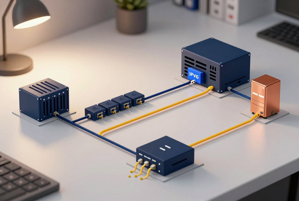
Important: The information in this post may or may not work. This is an experiment in having an AI agent design a network using only ingested technical books. The layout is automatically generated, has not been implemented or tested, and is not a guaranteed working network design. Treat it as a discussion piece, not a build guide.
What happens if you ask an AI to design a network and restrict its research to a library of technical books? It will find some useful patterns, combine them in a plausible way, and probably invent at least one failure mode the books were trying to warn us about.
So here is the experiment: a small regional research network with an IPv6-only field site, an old IPv4-only service, an IPv4 MPLS carrier core, and a backup path that takes a longer, stranger route across the public internet.
The design is believable enough to discuss. It is not validated enough to configure.
The imaginary network
Assume three locations:
- Field Site: sensors and workstations use IPv6 internally. The site has a primary carrier connection and a separate internet circuit.
- Archive Hub: the main data center, with the collection service and a connection to the carrier network.
- Relay Hub: a secondary site with an independent internet connection and a small standby collector. It can receive selected field traffic if the primary carrier path fails; buffered data can be synchronized to the Archive Hub after service returns.
There is also one legacy calibration service at the Archive Hub that only speaks IPv4. The field network should not need to become dual-stack just to reach that one old service.
Here is the intended shape:
Normal research traffic:
Field Site → customer edge router → provider edge → IPv4 MPLS core carrying the IPv6 VPN → provider edge at Archive Hub → collection service
Emergency transport:
Field Site → separate internet circuit → GRE tunnel protected by IPsec → Relay Hub standby collector; queued data syncs to the Archive Hub after recovery
Legacy service traffic:
IPv6 client at Field Site → normal primary route → NAT64 gateway at Archive Hub → IPv4-only calibration service
Path test traffic:
Dedicated diagnostic source → policy-based routing rule → GRE/IPsec backup tunnel, even while the primary route is healthy
The unusual part is that the IPv6 service traffic crosses a provider core that is still IPv4-based, and the backup path is a separately protected tunnel over the public internet. The second unusual part is deliberate: a small set of probes takes the backup route while everything else continues to use the primary path. That gives the operators a way to see whether the “emergency exit” is really an exit or just a very expensive diagram.
Primary path: IPv6 over an IPv4 MPLS core
The field network can stay IPv6-only while using a carrier’s existing IPv4 MPLS infrastructure. At the provider edges, an IPv6 VPN service can carry the site’s IPv6 routes across that IPv4-based core. The routers at the edge understand the customer’s IPv6 routes; the intermediate core transports labeled traffic without needing every internal router to run IPv6.
In the usual shorthand, this is the 6PE/6VPE family of designs. The important architectural idea is separation: customer IPv6 routing at the edges, IPv4 transport in the carrier core.
For this example, the Field Site announces only the prefixes it needs to reach the Archive Hub. The Archive Hub returns only the service prefixes the field needs. There is no reason for a tiny sensor network to receive a carrier-sized routing table, and there is certainly no need to hand it a default route to every interesting place in the world.
The primary path is intentionally boring. It is the route the application traffic should use on an ordinary day.
Backup path: GRE inside IPsec
The alternate path connects the Field Site to the Relay Hub over separate internet access. GRE provides a tunnel interface that can carry routed traffic. IPsec protects that traffic while it crosses the public network.
This is not “run both routes everywhere and hope.” The backup should carry a short, explicit list of routes: the collection service, essential management, and perhaps a small name-resolution service. It should not quietly become a second general-purpose internet gateway.
If the primary MPLS path fails, routing can move those selected prefixes to the backup tunnel. The far end must have a return route through the same tunnel for the affected flows. The design also needs a clean way to prevent the backup route from being re-advertised back into the primary domain and creating a loop.
That last sentence is where a real network engineer starts asking for diagrams, route tables, failure tests, and coffee.
The GRE/IPsec path has its own practical costs. Encapsulation consumes packet space. The tunnel endpoints need to remain reachable through the separate internet circuits. Keys must be managed. Routing must not accidentally send the tunnel’s own outer packets back inside the tunnel. Those details depend on the actual routers, carrier service, security policy, and addressing plan. This article does not resolve them.
The deliberately odd detour
The backup tunnel should not be tested only during an outage. By then, everyone is watching it, which is a terrible time to discover that it has never worked.
A narrow policy-based routing rule can steer selected diagnostic traffic through the GRE/IPsec tunnel while production traffic continues on the primary MPLS path. The probe can check reachability, latency, and whether the Relay Hub can return traffic to the Field Site. The standby collector gives the recovery tunnel a real destination instead of leaving it as a green light on a dashboard.
Keep the test flow easy to identify: a dedicated source subnet, dedicated probe destination, or separate routing context. Do not use a broad rule that catches ordinary user traffic by accident.
There is a catch: the request and reply must follow a path the endpoints and any stateful firewall can tolerate. If the probe leaves through the tunnel and its reply returns by MPLS, the path is asymmetric. That may be harmless for a stateless test, or it may fail at an appliance that tracks sessions and expects both directions to pass through it.
So the design does not pretend asymmetry is automatically clever. It makes the detour explicit, small, and observable. If a test requires a stateful middlebox, keep the forward and return legs together. If the goal is specifically to test asymmetric routing, isolate that experiment from production flows and label it accordingly.
Reaching the IPv4-only holdout
The calibration service is an old IPv4-only server at the Archive Hub. Rather than make every field device dual-stack, the hub can provide a NAT64 translation point for the specific service.
The path is then:
IPv6 field client → routed IPv6 network → translation gateway → IPv4 service
This translation point is a narrow bridge, not a general cure for old software. The service name must resolve in a way the IPv6 client can use, the translator must have a route to the IPv4 service, and the return traffic must find the same stateful translation path. Applications that embed IPv4 literals or make unusual assumptions may need more than address translation.
For that reason, the diagram puts translation at one well-defined hub. It does not spray translation across several sites and rely on luck to preserve session state. If the Archive Hub is unavailable, this example lets the legacy service fail visibly rather than pretending that the backup translator is a seamless replica.
That is a debatable choice. A production design might instead build redundant translation with shared state or a carefully tested failover mechanism. The source material is enough to raise the path-affinity issue; it is not enough to pick an implementation for an unknown environment.
A vendor-neutral build sheet
This is the part the first version left out. It is still a design sketch, not device-ready configuration, but it names the objects to create, the routes to exchange, and the order in which the pieces depend on one another.
1. Reserve the addressing and routing boundaries
Use an assigned IPv6 aggregate large enough to delegate a separate site prefix to each location. For illustration only, the following addresses come from the documentation range and must not be used on a live network:
| Purpose | Example prefix |
|---|---|
| Field Site aggregate | 2001:db8:4101::/48 |
| Field sensors | 2001:db8:4101:10::/64 |
| Field management | 2001:db8:4101:20::/64 |
| Field path probes | 2001:db8:4101:30::/64 |
| Archive Hub aggregate | 2001:db8:4102::/48 |
| Archive collector | 2001:db8:4102:10::/64 |
| Relay Hub aggregate | 2001:db8:4103::/48 |
| Relay standby collector | 2001:db8:4103:10::/64 |
Give the Field Site, Archive Hub, and Relay Hub separate routing contexts. In platform terminology, that usually means a dedicated IPv6 VRF for this service at each provider edge and matching separation at the customer edges. Do not put the backup tunnel, management network, and user LAN into one undifferentiated routing table just because that is the easiest first screen in the GUI.
The real address plan must come from the organization’s allocation and the carrier’s design. These example prefixes exist only to make the relationships visible.
2. Bring up the primary IPv6 VPN
At each provider edge, create the service VRF and attach the customer-facing IPv6 interface to it. Establish the customer-edge to provider-edge IPv6 routing relationship and advertise only that site’s assigned prefixes.
Between provider edges, enable the VPNv6 route family over the carrier’s existing IPv4-reachable MPLS core. The provider edge needs the IPv6 route, an inner VPN label for the customer prefix, and the outer MPLS label to reach the remote provider edge. The transit core can remain IPv4-based; the service edges carry the IPv6 VPN state.
Import the Field Site, Archive Hub, and Relay Hub routes only into this research service. On the Field Site, accept the archive collector and any explicitly required service prefixes. On the Archive Hub, accept the field sensor and management prefixes. On the Relay Hub, accept the field prefixes needed to receive failover traffic. The exact route-target values and neighbor syntax depend on the carrier and router platform.
Once this is up, verify two separate things: the provider control plane has the expected VPNv6 routes, and the forwarding path actually carries packets through the MPLS core. A route appearing in a table is not proof that the application can use it.
3. Build the alternate transport before using it for traffic
Use the separate internet circuits as the IPv4 underlay for the Field Site to Relay Hub tunnel. Reserve stable, reachable IPv4 endpoint addresses at both ends. Put a host route for the remote tunnel endpoint through the physical internet gateway so the tunnel’s outer packets cannot accidentally recurse into the tunnel they are trying to reach.
Create a GRE tunnel interface with a local source and remote destination. Then configure the IPsec peer authentication, key exchange proposal, and packet-protection policy that will protect the GRE traffic. Apply that protection to the GRE path. The precise names and commands vary by platform; the order of operations is the useful part.
Assign a small point-to-point overlay subnet to the tunnel. Add only the Field Site and Relay Hub IPv6 prefixes required for the standby collector and management. Give these routes lower preference than the MPLS VPN routes so the primary path wins while it is healthy. At the Relay Hub, install the matching return routes for the Field Site prefixes through the same tunnel.
The Relay Hub should terminate the failover traffic locally at its standby collector. It should not need a second mysterious route through the Archive Hub while the carrier path is down. When the primary path returns, a separate application or replication process can move queued data back to the archive.
4. Add a small policy-routed probe
Create a probe source in the Field Site diagnostic subnet and a probe target at the Relay Hub. Match only that source and destination in a policy rule, then set the egress to the GRE/IPsec tunnel. Do not match all sensor traffic or all traffic to the Relay Hub.
Install the return route at the Relay Hub through the tunnel. If the test crosses a stateful firewall, define the reverse policy as well so both directions traverse the same inspection path. If the test is only meant to prove tunnel reachability, use a simple stateless probe and keep it outside application sessions.
Decide what happens when the tunnel is down. For a path test, dropping the probe is useful: it tells the operator the backup path is unavailable. Silently sending it over the MPLS route would make the dashboard green while testing the wrong path.
5. Add the IPv4-only service bridge
At the Archive Hub, place one NAT64 gateway in the IPv6-to-IPv4 service path. Give it reachability to the legacy IPv4 calibration server and advertise only the translation prefix to the Field Site. If clients use names, pair the translator with DNS64 or provide explicit IPv6-compatible service records.
Keep the return path for translated sessions at that same gateway. The indexed transition material warns that translator-based sessions can fail when their packets take asymmetric paths. A redundant translator can be designed, but its state and failover behavior need a separate test; this sketch does not claim that two independent translators can transparently share sessions.
6. Verify the routes in both directions
Before relying on the layout, record the expected path for each flow:
- Field sensor to Archive collector: MPLS VPN in both directions.
- Field sensor to Relay standby collector during failover: GRE/IPsec in both directions.
- Diagnostic probe: GRE/IPsec even while MPLS is healthy, with the return path kept in the same routing context.
- IPv6 client to legacy IPv4 calibration server: NAT64 at the Archive Hub, with translated return traffic through the same gateway.
Then test the failure states deliberately: withdraw the primary VPN route, confirm the selected prefixes move to the tunnel, confirm the Relay Hub can reply, restore the MPLS route, and verify that the primary again becomes preferred. Test the actual maximum packet size through both paths, not just a small ping. Confirm the translator with the real calibration application.
That is a build sequence. It is still not a configuration file: interface names, authentication, route policy syntax, timers, prefix filtering, firewall rules, MTU values, and the carrier’s 6VPE service all have to be chosen for a real environment.
Route intent at a glance
| Traffic | Preferred route | Alternate route | Special concern |
|---|---|---|---|
| Sensor data to archive | IPv6 VPN across IPv4 MPLS | GRE over IPsec to Relay Hub standby collector; synchronize later | Keep the route set narrow and return paths known |
| Site management | Primary VPN, with essential management prefixes on backup | GRE over IPsec | Do not expose management broadly just because a tunnel exists |
| Backup-path probes | Deliberate PBR detour through GRE/IPsec | Primary path for comparison | Track forward and return paths; isolate from normal traffic |
| IPv6 client to legacy IPv4 service | NAT64 at Archive Hub | None in this sketch | Translation state and return path stay at the same gateway |
| Ordinary internet access | Local site policy, outside this sketch | Not specified | The experiment does not define a general internet-edge design |
The table is more honest than a big topology picture because it says where the design stops. It does not specify an address plan, routing protocol timers, firewall rules, cryptographic suite, link speeds, provider contract, or service-level objective. Those are not minor omissions. They are most of the work in turning an idea into a working network.
What could go wrong
A few predictable ways this sketch could fall over:
- MTU and fragmentation: the 6VPE path, GRE, and IPsec each add constraints. A packet that fits the primary path may fail in the tunnel. Path MTU discovery and tunnel sizing need end-to-end testing.
- Asymmetric return traffic: a route change, policy rule, or second hub could send replies through a different stateful firewall or translator.
- Route leakage: a backup prefix could escape its intended routing context or return to the domain that originated it.
- Recursive tunnel routing: the public address used to reach the GRE/IPsec endpoint could itself be routed into that tunnel.
- Partial failure: the tunnel may be up while the service behind the Relay Hub is down, or the carrier route may still exist while packets are black-holed.
- False confidence from probes: a small ICMP test can succeed while the application path fails because of filtering, translation, MTU, or service dependencies.
- The lonely legacy service: NAT64 may solve address-family mismatch while leaving application assumptions untouched.
None of those are exotic edge cases. They are the difference between “the drawing has arrows” and “the network behaves properly when something breaks.”
How an engineer would validate it
Before anyone considered implementation, the design would need to be compared with real requirements and hardware, then tested in a lab.
At minimum:
- Confirm that the carrier actually supports the required IPv6 VPN service over its MPLS core.
- Confirm which IPv6 prefixes each site should exchange, and which routes must never cross the boundary.
- Test primary and backup paths independently, including the reverse direction.
- Measure MTU through the full encapsulation stack and test path MTU discovery.
- Verify that the tunnel endpoint remains reachable outside the tunnel.
- Test failover during active sessions and document which sessions are expected to survive.
- Test the NAT64 service with the real application, not only a ping.
- Observe what the policy-routed probes do when the tunnel, route, hub, or destination fails.
- Review firewall state, logging, key rotation, monitoring, and operational ownership.
- Have someone who will be responsible for the network review the design before it leaves the lab.
That list is not a guarantee either. It is a start.
What the books gave us—and what they didn’t
The ingested technical pages surfaced several useful building blocks: IPv6 VPN service over an IPv4 MPLS core, GRE carried inside IPsec, policy-based routing for selected flows, NAT64 for reaching IPv4-only services, and the operational hazard of asymmetric paths. They also surfaced the need to think about MTU and fragmentation when tunnels are layered.
The books did not tell us that these pieces belong together in this exact topology. They did not provide the missing environment details. They did not test the design. The AI did the stitching—and stitching is not the same thing as engineering validation.
That is the experiment. The layout may be useful as a conversation starter. It may also contain a subtle mistake that becomes obvious to someone who has built one of these for real. Either outcome is more interesting than pretending a generated diagram has been through a change window.
This is an automatically generated conceptual network layout based only on technical documents found in the ingested technical-book indexes. It has not been implemented, simulated, or reviewed by a network engineer. It is not guaranteed to work and should not be used as a deployment plan.